
- All
- Product Name
- Product Keyword
- Product Model
- Product Summary
- Product Description
- Multi Field Search
Views: 124 Author: Site Editor Publish Time: 2026-08-11 Origin: Site
High-speed CNC machining exposes every structural weakness in a frame. Deflection and vibration directly compromise part tolerances. You cannot hide a weak mechanical foundation behind advanced software compensation. Upgrading control systems or spindles yields minimal return if the underlying motion system suffers. Issues like backlash, high static friction, or lateral play will destroy your cut quality.
Upgrading to a properly specified Linear Guide transforms structural rigidity and positioning reliability. This single upgrade moves a machine from unpredictable variance to repeatable, verifiable machine accuracy. You will discover exactly how square profile guides outperform legacy motion systems. We will explore essential sizing metrics, preload classes, and stringent alignment protocols. Understanding these factors ensures your next machine build or retrofit delivers absolute precision.
Profile linear guides replace rolling friction with highly rigid, recirculating ball or roller bearing blocks, minimizing mechanical deflection under heavy cutting loads.
Selecting the correct precision grade and preload class is more critical than buying the most expensive option; over-specifying leads to unnecessary friction and costs.
A precision rail is only as accurate as its mounting surface; stringent alignment and surface preparation are mandatory to realize accuracy gains.
Replacing legacy CNC components (like round shafts or dovetails) with square profile guides significantly reduces backlash and stick-slip errors during micro-movements.
Many legacy machines rely on unsupported round rails or sliding dovetail ways. These older systems present significant structural limitations. Unsupported round shafts bend easily under cutting forces. This bending causes the tool to deflect away from the intended path.
Dovetail ways suffer from a different issue known as stick-slip. Static friction in a sliding dovetail is much higher than kinetic friction. When the motor attempts a microscopic movement, the axis resists until enough force builds up to break the stiction. The axis then lurches forward, overshooting the target coordinate. This phenomenon creates terrible surface finishes and destroys dimensional tolerances. Furthermore, dovetails wear unevenly over time. This wear introduces slop, leaving the machine highly vulnerable to chatter.
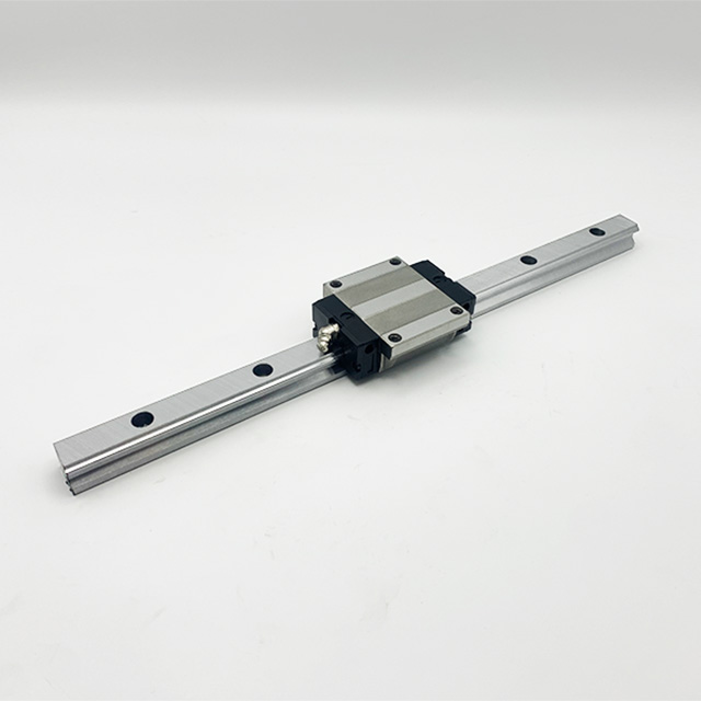
Modern profile guides solve these fundamental flaws. A modern CNC linear guide features a carefully engineered geometric profile. The bearing block wraps around a square rail. Inside the block, multiple rows of recirculating steel balls or rollers make contact at specific angles.
Most premium guides use a 45-degree contact angle. This geometry provides equal load-carrying capacity in all four directions. The system resists downward radial forces, upward reverse-radial forces, and side-to-side lateral forces equally well. When a heavy endmill plunges into hardened steel, the forces push the spindle in unpredictable directions. The four-way equal load capacity keeps the spindle rigidly locked on its path.
Aggressive toolpaths generate severe resonance. Continuous contact within the bearing block reduces this vibration. Legacy systems leave microscopic gaps where parts can rattle. Recirculating blocks maintain constant, preloaded contact against the raceways.
This unbroken contact acts as a mechanical dampener. It absorbs the high-frequency vibrations generated by the cutting tool. Lower resonance translates directly into superior surface finishes. Parts come off the machine requiring less secondary polishing. Tool life also increases because the cutting edges do not micro-fracture from chatter.
Best Practice: Always evaluate the dynamic load rating. Choose a size where your average cutting forces do not exceed 20% of the maximum dynamic load. This ensures optimal vibration dampening.
Manufacturers classify rails using standard industry accuracy grades. These grades dictate the allowable variance in height, width, and running parallelism. The common tiers include:
Normal (N)
High (H)
Precision (P)
Super Precision (SP)
Ultra Precision (UP)
Implementation Reality: You must understand the point of diminishing returns. Buying an "Ultra Precision" rail for a hobby-grade aluminum router is a complete waste of capital. Aluminum extrusions fluctuate wildly in straightness. The mounting surface will warp the rail, instantly negating the UP grade. Normal or High grades perfectly suit bolted aluminum frames. Reserve P, SP, and UP grades for heavily ribbed, precision-ground cast iron bases.
Preload introduces internal force between the rolling elements and the raceways before any external load applies. This eliminates internal clearance and boosts rigidity. However, choosing the correct preload requires balancing multiple factors.
Here is a comparison of standard preload configurations:
Preload Class | Internal State | Best Application | Trade-offs |
|---|---|---|---|
Clearance (Z0) | Microscopic gap present | Light duty, simple automation | Lowest rigidity, high speeds possible, no heat buildup |
Light Preload (ZA) | Zero gap, slight compression | Wood routers, laser cutters, 3D printers | Good balance of stiffness and low friction |
Heavy Preload (ZB) | High internal compression | Metalworking mills, heavy lathes | Maximum rigidity, generates heat, requires strong motors |
Decision Framework: Higher preload sharply increases rigidity. This translates to better accuracy during heavy cuts. The trade-off involves friction. Heavy preload introduces thermal expansion risks during rapid movements. It also requires more powerful servo motors to overcome the internal drag.
The rolling elements dictate the load-to-deflection ratio. Ball types utilize spherical bearings. They offer point contact against the raceway. This creates lower friction, enabling extreme rapid traverse speeds. Ball types excel on high-speed routers, plasma tables, and laser cutters.
Roller types utilize cylindrical rollers. They offer line contact against the raceway. Line contact massively increases the contact area. This dramatically improves the load-to-deflection ratio. When heavy forces apply, roller blocks deflect far less than ball blocks. We strongly recommend roller types for heavy-duty metal milling and rigid tapping applications.
Engineers often over-specify components. You must establish clear operational benchmarks before selecting parts. Do not guess your requirements. Define your target part tolerance first. If you machine aerospace components, you need micron-level repeatability. If you cut cabinet plywood, a variance of a few thousandths of an inch is perfectly acceptable.
Next, evaluate your rapid traverse speeds and duty cycles. High-speed, continuous movement generates heat. Heavy duty cycles demand robust sealing and careful lubrication planning. Establish these criteria to build a sensible specification matrix.
Different industries demand entirely different engineering priorities. Let's examine two distinct categories.
Woodworking environments present specific challenges. Fine dust penetrates everywhere. In these applications, you must focus heavily on dust-sealing capabilities. High-speed ratings matter more than extreme load capacities. Cutting wood generates low cutting forces compared to steel. A light-preload, ball-type system with double-lip end seals serves this application perfectly.
Milling hardened tool steel creates massive lateral forces. Dust is less of an issue, but hot metal chips and corrosive coolant pose severe threats. For metalworking, you must prioritize heavy preload and high structural rigidity. A heavy-preload, roller-type system resists tool deflection brilliantly. You must also specify steel scraper plates to push hot chips away from the bearing blocks.
Common Mistake: Do not install heavy-preload blocks on machines using NEMA 23 stepper motors. The motors will stall trying to push the highly preloaded blocks. Match your drive system power to your preload choice.
Buying a highly accurate precision rail guarantees nothing by itself. The rail conforms exactly to the surface underneath it. This presents a massive implementation risk. If you mount a perfectly straight rail onto a bowed, wavy, or uneven surface, the rail will bend to match the defect.
This trap destroys machine accuracy. The bearing blocks will bind as they travel across the warped section. Premature wear occurs rapidly. The internal balls crush against the raceway, destroying the micron-level precision you just paid for.
Raw T-slot aluminum extrusions rarely achieve stated accuracy metrics. Extrusion manufacturing involves pulling hot metal through a die. The cooling process introduces twists, bows, and dips. Bolting high-grade rails directly to these raw extrusions is a critical error.
To realize true accuracy gains, the mounting surface requires preparation. Industrial machines utilize heavily ribbed cast iron or steel bases. Engineers then machine the rail mounting ledges in a single setup using a massive gantry mill. They precision-grind these ledges to ensure absolute flatness and parallelism. If you must use aluminum extrusions, consider epoxying a precision-ground steel flat bar to the extrusion first, creating a verified flat reference plane.
Proper installation demands strict alignment procedures. Never bolt down both rails simultaneously. Follow this systematic approach to prevent microscopic binding:
Clean the surfaces: Wipe down the mounting ledges and the rail bottoms using a degreaser. A single metal chip trapped under the rail ruins the alignment.
Establish the Master Rail: Choose one rail to act as your reference. Press it firmly against the machined reference shoulder on your base.
Sequential Torqueing: Insert the mounting bolts on the master rail. Torque them starting from the center and working outward to the ends. Use a calibrated torque wrench.
Verify Straightness: Run a dial indicator along the master rail to confirm it sits perfectly straight.
Align the Subordinate Rail: Mount the second rail loosely. Attach the gantry plate to the bearing blocks on both rails. Slowly move the gantry back and forth. The gantry's movement naturally forces the subordinate rail into parallel alignment. Torque the subordinate rail bolts progressively as the gantry passes over them.
Mechanical precision degrades instantly without proper lubrication. You must supply a continuous microscopic film of lubricant between the rolling elements and the raceways. Specify the correct lubrication system during the design phase.
Grease provides excellent protection for short-travel, moderate-speed applications. It stays in place and helps seal the block against contaminants. Oil systems excel in high-speed, continuous-duty machines. Oil flows easily, washing away microscopic debris and dissipating heat.
Highlight the risk of lubricant starvation in vertical configurations. Z-axis setups fight gravity. If you pump oil into the top of a Z-axis bearing block, it quickly drains out the bottom. Always specify Z-axis blocks with lubrication ports positioned to fight gravity, or use thick lithium-soap grease that resists dripping.
Swarf and coolant will destroy internal ball tracks within days. Evaluate your operating environment to determine necessary ingress protection.
End Seals: Standard rubber wipes at both ends of the block. They keep light dust out and grease in.
Bottom Seals: Prevent debris from entering up through the bottom gap between the block and the rail.
Scraper Plates: Essential for metalworking. These steel plates mount outside the rubber end seals. They physically scrape away hot, sharp metal chips that would otherwise melt through rubber seals.
You cannot wait for complete failure. Establish baseline metrics for inspecting play. Use a dial indicator to push against the spindle housing. Measure the deflection under a known static load. Record this number when the machine is brand new.
Check this measurement every six months. If the deflection increases significantly, wear has occurred. Look for early signs of spalling. Spalling happens when microscopic flakes of steel break away from the raceway due to fatigue. You will often notice a gritty feeling or a slight hum during travel. Catching this early allows you to replace the worn CNC components before catastrophic failure impacts your part quality.
Profile guides serve as the foundation for repeatable mechanical precision. They completely eliminate the slop, stick-slip, and rapid wear associated with legacy round shafts and dovetails. However, they only deliver these benefits when matched to the correct load profile. You must respect the engineering prerequisites. Strict alignment tolerances and rigid mounting surfaces are absolute necessities.
Take action by auditing your current machine setup. Measure your existing deflection limits using a dial indicator. Map out your required part tolerances based on your most demanding clients. Before purchasing new hardware, consult a manufacturer's load-calculation software. Speaking with an application engineer can also prevent costly over-specification. Proper planning guarantees a motion system that performs reliably for years.
A: Not automatically. It eliminates rail-induced play, but exposes other weaknesses in the machine frame, ball screws, or motor couplers. Systemic rigidity is required. If your frame flexes under load, a high-precision guide will not fix the bad cuts. You must upgrade the entire structural path.
A: Size should be dictated by dynamic load ratings and moment loads, not just physical footprint. Calculate the spindle weight, gantry mass, and peak cutting forces. Consult the manufacturer's load charts. Selecting a size based purely on visual proportions often leads to catastrophic overload or unnecessary mass.
A: Binding is almost always caused by a lack of parallelism between parallel rails. It can also stem from an uneven mounting surface. This unevenness forces the bearing block to flex as it travels. Loosen the subordinate rail, run the gantry back and forth to self-align, and retorque carefully.
A: It depends on travel distance and operating environment. Industry best practice requires checking lubrication intervals based on hours of operation or distance traveled (e.g., every 100km of travel). Always factor in the specific viscosity of the grease or oil used and the level of environmental contamination.


