
- All
- Product Name
- Product Keyword
- Product Model
- Product Summary
- Product Description
- Multi Field Search
Views: 0 Author: Site Editor Publish Time: 2026-08-27 Origin: Site
In linear motion systems, the long threaded screw often takes the spotlight. However, the nut assembly is where the actual load transfer and critical motion control happen. Selecting the wrong configuration immediately compromises the entire assembly. You might experience excessive backlash during operations. Systems can suffer from premature wear or catastrophic failure under heavy dynamic loads.
For engineers and system integrators at the specification stage, evaluation goes beyond matching physical dimensions. It requires a highly calculated balance. You must align preload requirements, internal recirculation mechanics, and specific mounting architectures to meet strict performance targets. We will explore how proper ball nut design directly impacts positional accuracy. You will learn to navigate the intricate trade-offs between system rigidity and bearing lifespan. By understanding these mechanical nuances, you can ensure your motion system operates efficiently and reliably.
Mounting matters: The choice between a flanged ball nut and a cylindrical design dictates system rigidity, footprint, and installation complexity.
Speed is bottlenecked by recirculation: A high speed ball nut relies on optimized internal return mechanisms to handle elevated DN values without destroying the bearings.
Preload is a direct trade-off: Increasing preload eliminates backlash and boosts precision, but fundamentally increases friction and reduces overall bearing life.
Quality defines repeatability: Sourcing true precision components ensures consistent raceway geometry, preventing torque spikes and maintaining long-term positional accuracy.
Suboptimal component choices consistently result in systemic machine failures. These failures range from resonant vibration at high speeds to catastrophic lost motion during directional changes. When precision degrades, the entire automation process suffers. Engineers often underestimate the sheer dynamic stress placed on these moving components. A poorly specified nut will quickly become the weakest link in your mechanical chain.
Failure carries steep operational penalties. Machine downtime stops production lines completely. Excessive maintenance intervals drain engineering resources. Compromised end-product quality damages brand reputation. You must view component selection as a core reliability strategy rather than a simple purchasing task. Replacing damaged linear assemblies requires extensive labor and recalibration.
An optimized setup maximizes the dynamic load rating. It simultaneously maintains the exact level of rigidity required for your application's specific duty cycle. Success means hitting your target lifecycle without over-engineering the solution. We evaluate success by measuring long-term repeatability under continuous payload stress. When you choose correctly, the system operates quietly, accurately, and requires minimal intervention over its designated lifespan.
Mounting architecture defines how forces transfer from the actuator to the carriage. Engineers primarily choose between flanged and cylindrical configurations. Each style presents distinct mechanical advantages and specific installation challenges. Your spatial envelope and rigidity requirements will drive this decision.
A flanged ball nut features an integrated mounting collar. This flange allows direct, rigid bolting to the moving carriage or load platform. The mechanism provides a substantial surface area for secure fastening. It is best for heavy-duty applications requiring maximum axial stiffness. It drastically simplifies system alignment during assembly. However, you must accept certain trade-offs. Flanged units require more physical envelope space. They carry a heavier mass compared to alternative sleek designs.
Cylindrical designs present a much slimmer profile. They rely on external threads or precision keyways. These features lock the component securely into a custom housing. They are best for highly compact assemblies. Aerospace applications and specialized OEM housings heavily utilize them. Implementation risk remains high. You must maintain extremely tight machining tolerances on the mating housing. Loose fits cause radial play. Radial play immediately leads to uneven raceway wear and rapid failure.
Consider the structural comparisons below when planning your assembly layout:
Feature | Flanged Configuration | Cylindrical Configuration |
|---|---|---|
Mounting Interface | Integrated collar for direct bolting | External threads or locking keyways |
Installation Complexity | Low (simple alignment) | High (requires precise mating housing) |
Space Requirement | High radial envelope | Highly compact profile |
Primary Risk | Excessive mass for light payloads | Radial play from poor housing tolerance |
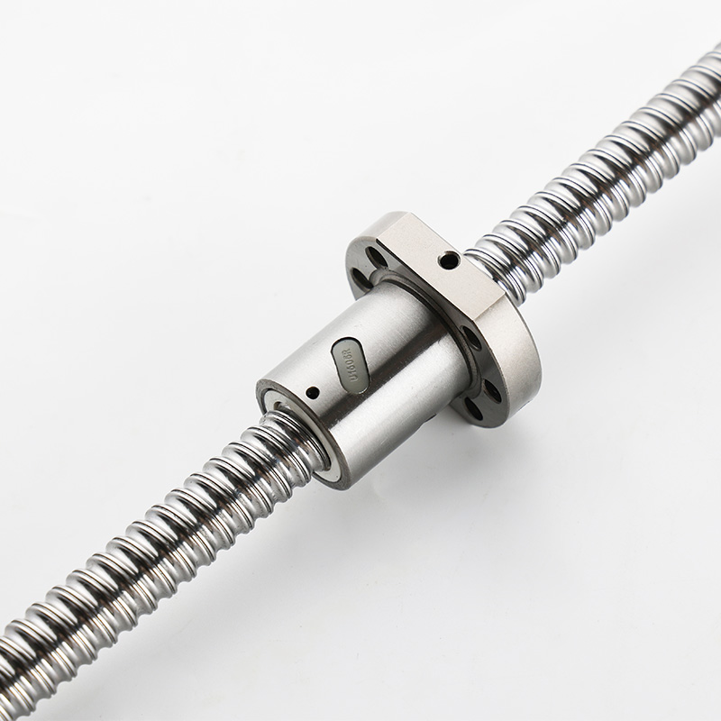
Recirculation paths dictate how smoothly steel balls travel through the threaded circuit. As shaft rotational speed increases, internal physics change dramatically. Centrifugal force pushes the ball bearings outward. This intense force threatens to jam or permanently damage the return mechanism. Managing this velocity challenge requires specialized internal architecture.
Standard designs often use external return tubes. These curved metal pipes guide balls over the nut's exterior. They are cost-effective. They work perfectly for moderate speeds. However, they become problematic at high RPMs. External tubes are highly prone to vibration. They generate significant acoustic noise under fast acceleration.
Internal return systems are fundamentally different. They use precision-machined end-caps or internal button deflectors. This internal routing is essential for a high speed ball nut. It keeps the outer diameter perfectly compact. The design drastically reduces operational noise. More importantly, it safely manages elevated centrifugal forces without jamming the circuit.
When evaluating for speed, do not rely on linear velocity alone. Buyers must look at the manufacturer's specified maximum DN value. You calculate DN by multiplying the nominal shaft diameter (in mm) by the maximum rotational speed (in RPM). A high DN rating confirms the internal deflectors can survive intense kinetic energy.
The chart below summarizes recirculation performance metrics:
Recirculation Type | Speed Capability (DN Limit) | Noise Profile | Best Use Case |
|---|---|---|---|
External Tube | Up to 70,000 | Moderate to High | Standard automation, slow lifting |
Internal Button | Up to 100,000 | Low | Compact actuators, CNC feeding |
End-Cap Deflector | 100,000 to 150,000+ | Very Low | High-speed positioning stages |
Preload is a critical specification for precision motion. It deliberately introduces internal tension between the bearings and the raceway. This tension completely eliminates axial backlash. Axial backlash is the lost motion you experience when reversing direction. Preloading increases the overall stiffness of the nut-to-screw interface. This rigidity proves critical for exact CNC machining and automated dispensing systems.
Manufacturers achieve preload through two primary mechanical methods. Each serves a different payload class.
Oversized Ball Preload: This method uses a single nut. Factory technicians load steel balls slightly larger than the raceway gap. It is highly cost-effective. It keeps the assembly very compact. However, it remains limited to lighter loads. You typically cap this preload at 5% of the dynamic load rating.
Double Nut Preload: This method uses tension or compression principles. A precisely ground spacer sits between two separate nuts. This configuration handles extreme loads. It offers superior structural stiffness. The trade-off involves a much larger physical footprint and higher manufacturing costs.
Preload creates a direct mechanical paradox. Higher preload naturally generates more internal friction. More friction produces excess heat during continuous duty cycles. System designers must precisely calculate the exact preload required to achieve desired accuracy. Over-preloading provides no extra positional benefit. Instead, it will exponentially degrade bearing life. High-friction systems also demand heavier, more frequent lubrication protocols. You must balance the need for zero backlash against your target maintenance intervals.
Manufacturing realities dictate mechanical performance. Not all production facilities maintain the same rigorous standards. The physical consistency of the internal raceway directly dictates operational smoothness. Slight geometric variations cause severe torque spikes during travel. You need exact tolerances to guarantee repeatable motion over thousands of cycles.
Engineers evaluate precision components by examining two core manufacturing processes. The first is raceway formation. Precision grinding yields vastly superior results compared to standard rolling. Ground raceways are strictly required for high-accuracy positioning. They meet stringent ISO classes from IT1 down to IT5. Rolled threads cannot achieve this micro-level consistency.
The second marker is metallurgical heat treatment. Advanced carburizing hardens the material surface deeply. Induction hardening provides another excellent alternative. Proper hardening ensures the internal raceway withstands repetitive hertzian contact stress. Without deep hardening, the metal surface will begin spalling under heavy dynamic loads.
Never assume precision based solely on marketing claims. Buyers should demand documented testing data. Request detailed lead accuracy reports from the factory. Ask for continuous torque variation charts. These documents verify the manufacturer actually tested the specific batch. Rigorous documentation proves you are receiving true industrial-grade parts capable of sustained performance.
Navigating catalogs requires a systematic elimination process. Use this sequential framework to narrow down your optimal configuration.
Define the Spatial Envelope: Measure your available carriage space. Determine if the housing can easily accommodate a large flanged interface. If space is tightly constrained, a cylindrical or compact profile becomes completely mandatory.
Calculate Load vs. Speed: Map your maximum dynamic load against the required operational RPM. Calculate your DN value immediately. If your DN value exceeds 70,000, immediately filter your search. Look exclusively for internal-recirculation high-speed designs to prevent jamming.
Determine Backlash Tolerance: Evaluate your true accuracy needs. If the application requires sub-micron repeatability, you must specify a double-nut preload. If slight backlash remains acceptable, save your budget. For example, vertical lifting with a constant gravity bias naturally eliminates backlash. In such cases, use a zero-preload single nut.
Assess Environmental Factors: Look closely at the operating environment. Standard configurations fail rapidly in dirty settings. Factor in custom wiper designs. Specify heavy-duty labyrinth seals if operating in environments with heavy particulate contamination or metal shavings.
The performance limits of any linear actuator are inherently tied to its internal nut architecture. Moving beyond basic dimensional matching is crucial for long-term reliability. Engineering teams must rigorously evaluate mounting styles, internal recirculation paths, and precise preload calculations. This systematic approach guarantees positional accuracy. It protects system rigidity without prematurely sacrificing bearing life.
To move forward effectively, calculate your system’s absolute maximum DN value. Map your precise load profile against standard manufacturer catalog specifications. Determine your exact tolerance for axial backlash before selecting a preload method. If standard configurations cannot meet your spatial or speed requirements, consult directly with a trusted manufacturer. They can engineer a custom-machined interface to ensure your motion system performs flawlessly under pressure.
A: A flanged design provides a simpler, highly rigid mounting interface. It bolts directly to the load carriage. This reduces the complex machining tolerances required for the mating housing. It ensures excellent axial stiffness for heavy-duty industrial applications.
A: Preload purposefully increases internal friction to completely eliminate backlash. This added friction creates a consistent rotational drag. Consequently, your servo or stepper motor will require higher continuous torque to drive the system smoothly, especially during initial startup.
A: You should evaluate high-speed specific designs when your application's DN value exceeds 70,000. Calculate DN by multiplying nominal shaft diameter in mm by maximum rotational speed in RPM. Internal end-cap recirculation is also required when acoustic noise reduction is a primary design goal.
A: Generally, no. For single nuts using oversized balls, technicians permanently set the preload at the factory. Double-nut configurations rely on precision-ground metal spacers. Altering preload in the field risks misaligning the bearings. This causes rapid system failure and should only be handled by the manufacturer.


