
- All
- Product Name
- Product Keyword
- Product Model
- Product Summary
- Product Description
- Multi Field Search
Views: 0 Author: Site Editor Publish Time: 2026-08-21 Origin: Site
Selecting a linear drive mechanism demands ultimate precision. Specifying the wrong Ball Nut compromises your entire assembly. It often leads to premature fatigue, unacceptable backlash, and severe thermal expansion issues down the line. Many engineers focus heavily on the screw shaft during the design phase. However, ball screw performance is rarely limited by the shaft itself. Instead, the nut strictly dictates overall load capacity, system rigidity, and operational lifespan.
Making an improper choice guarantees early mechanical failure. We aim to provide an evidence-based, engineering-focused framework for this crucial component. You will learn how to evaluate different configurations, calculate dynamic loads, and choose proper return mechanisms. This guide actively bridges the gap between theoretical calculations and true operational reliability in the field.
Preload determines rigidity: Selecting the correct preload method (oversized ball vs. double nut) balances stiffness against frictional heat generation.
Space constraints dictate configuration: Flanged, cylindrical, and threaded nut bodies serve distinct mounting and spatial limitations.
Return mechanisms impact speed and noise: Internal deflectors, external tubes, and end-cap returns each possess distinct maximum speed (DN value) thresholds.
Theoretical life requires environmental derating: Dynamic load ratings must be adjusted for vibration, contamination, and lubrication realities to predict actual field life.
The nut serves as the primary performance bottleneck in any screw-driven setup. It acts as the singular load-bearing interface between the rotating shaft and the moving carriage. Because it houses the recirculating steel balls, it also represents the main source of friction and wear. Your overall linear motion system relies entirely on this component to translate rotary torque into precise linear thrust. If the nut fails, the machine stops.
Poor selection quickly reveals itself through catastrophic failure modes. You might observe brinelling on the raceways. This occurs when excessive static loads cause permanent indentations in the metal. You may also see ball spalling. Spalling typically results from inadequate lubrication, causing the rolling elements to flake apart under stress. Another common symptom is the sudden loss of positioning accuracy. Wear increases the internal clearance, resulting in unacceptable mechanical play.
Engineers must balance competing variables to achieve operational success. Establishing a proper tradeoff matrix is essential. Maximizing rigidity and load capacity inherently increases internal friction. Higher friction generates more heat. More heat subsequently reduces your maximum allowable travel speed. You cannot maximize every variable simultaneously. You must prioritize specific metrics based on your unique application demands.
Choosing the correct physical housing determines how easily you can integrate the assembly into your machine. Space constraints typically dictate this decision. Flanged configurations represent the industry standard. They are best for applications requiring high axial load transfer. They offer straightforward bolt-on integration. You simply bolt the flange directly to the moving carriage. However, they draw a major drawback. They require a significantly larger radial envelope.
Cylindrical bodies offer a more compact alternative. They are best for highly space-constrained designs. They eliminate the bulky flange entirely. You must consider their specific integration requirements, though. They demand precise bore tolerancing inside your housing. They also require a mechanical keyway. Without a keyway, the entire cylinder will rotate freely instead of driving the load.
Threaded housings serve distinct specialty applications. They feature an external thread on the body itself. They are best for integration into custom housings. Many engineers use them when replacing pneumatic cylinders with electromechanical actuators. They allow for highly secure, low-profile locknut mounting.
Return mechanisms dictate how the steel balls recirculate. You must evaluate these options carefully. External return tubes are highly cost-effective. They sit outside the nut body. Unfortunately, they generate higher noise levels. Internal deflectors offer a superior alternative for certain leads. They are highly compact and run much quieter. They suit fine-lead applications perfectly. End-cap returns provide the ultimate solution for high-speed travel. They route the balls through the end caps, making them ideal for high-lead configurations.
The chart below summarizes the primary physical configurations for easy comparison.
Body Configuration | Primary Advantage | Major Limitation | Best Application |
|---|---|---|---|
Flanged | Simple bolt-on mounting | Requires large radial space | Standard industrial machines |
Cylindrical (Keyed) | Highly compact footprint | Requires strict bore tolerances | Space-restricted automation |
Threaded | Secure, low-profile locking | Complex custom machining needed | Pneumatic cylinder replacements |
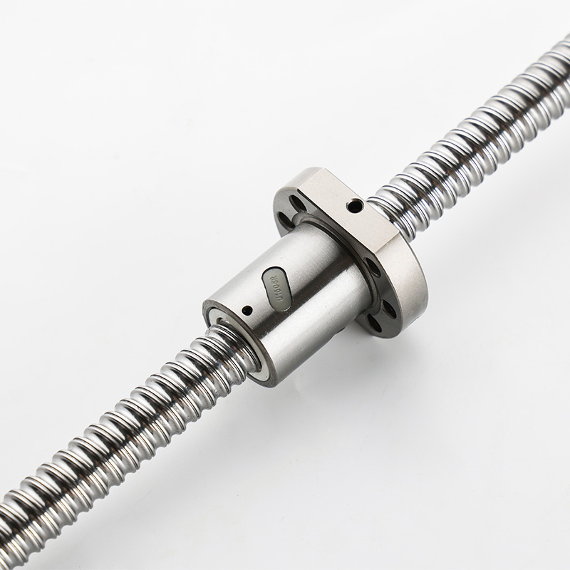
You cannot achieve sub-micron positioning without eliminating axial play. This is the exact purpose of applying a preload. Preloading removes internal clearances between the balls and the raceway. It significantly increases system rigidity. It ensures highly accurate positioning under reversing loads. If your machine changes direction frequently, you need a properly specified preload ball nut to maintain tight tolerances.
Engineers utilize three primary strategies to achieve this condition. Each strategy offers specific benefits and drawbacks.
Oversized Ball Preload (Single Nut): This mechanism uses balls slightly larger than the raceway clearance. It forces a tight fit. It is ideal for cost-sensitive, space-restricted applications. It provides moderate stiffness without demanding extra housing length.
Double Nut Preload: This mechanism utilizes two distinct nuts. Manufacturers place a precision-ground spacer between them. The spacer tensions the two nuts against each other. It is ideal for heavy machine tools requiring maximum rigidity. It easily handles the highest offset loads in extreme industrial environments.
Offset Pitch Preload: This mechanism shifts the thread pitch directly in the middle of a single nut housing. The slight offset creates interference. It is ideal for achieving high rigidity within a standard single-nut footprint. It bridges the gap between oversized balls and double-nut designs.
Risk mitigation remains critical during specification. You must explicitly warn your assembly teams against over-preloading. Excessive tension exponentially reduces L10 fatigue life. It forces the rolling elements to grind against the raceway under immense pressure. This generates rapid friction and intense heat. Over-preloading ultimately requires advanced thermal compensation systems to prevent the screw shaft from expanding and warping.
Choosing the correct dimensional ratings separates a functional design from a reliable one. You must fundamentally understand the difference between dynamic and static load ratings. The Static Load Rating (C0) prevents permanent plastic deformation. It dictates how much stationary shock load the raceways can absorb. Exceeding C0 causes indentations. These indentations destroy smooth travel forever.
The Dynamic Load Rating (C) serves a completely different purpose. You use C to calculate the L10 fatigue life. The L10 metric predicts exactly when 10% of identical systems will show initial metal flaking. You base your maintenance schedules on this calculation. A robust precision ball nut requires an accurate L10 calculation to guarantee machine uptime.
Speed limitations require equal attention. You must calculate the maximum safe rotational speed using the DN value. The DN value multiplies the nominal diameter (D) by the rotational speed (N). Every return mechanism possesses a strict DN threshold. External tubes might cap out at a DN of 70,000. Internal deflectors might reach 100,000. End-cap systems push even higher. Exceeding the DN limit causes the rolling elements to shatter the return guides.
Accuracy grades finalize the dimensional evaluation. You must match the internal tolerances to the screw's lead accuracy. Global standards utilize specific grades like C3, C5, and C7. A C3 grade offers extremely tight travel variation. It suits aerospace and semiconductor manufacturing. A C7 grade provides looser tolerances. It perfectly suits basic transport and woodworking equipment. Mismatching the grade wastes money and compromises repeatability.
Theoretical calculations fall apart if you ignore the physical operating environment. Contamination defense serves as your primary shield against early failure. You must assess wiper types based on specific threats. Felt wipers work well for capturing fine wood dust. Plastic or urethane wipers block heavier metal chips and coolant spray. Brush wipers serve cleanroom environments by generating minimal particulate matter.
Lubrication access requires proactive design choices. You must design your carriage to accommodate grease fittings or automated oil delivery lines. A dry raceway fails rapidly. It does not matter how high your dynamic load ratings are. Without an unbroken lubrication film, steel grinds against steel. Oil delivery systems flush out contaminants actively. Grease provides longer-lasting boundary protection but traps dirt if seals fail.
Alignment tolerances often trap inexperienced engineers. You must address the severe risks of side-loading and bending moments. Nuts are designed strictly for axial loads. They cannot handle radial forces. If you apply a radial load, the rolling elements pinch unevenly. This drastically reduces L10 life. You must employ external linear guides to handle all radial and moment forces. The screw should only push and pull.
Navigating countless vendor catalogs feels overwhelming. You need a structured approach to narrow down your options. Following a standardized ball nut selection framework guarantees consistent, reliable outcomes for every project.
Application Profiling: Define the absolute basics first. Document the required stroke length. Identify the maximum payload. Establish the required travel speed. Set a firm target for positioning accuracy.
Calculate Equivalent Loads: Do not just look at static weight. Factor in aggressive acceleration forces. Account for varied duty cycles. A machine running 24/7 requires vastly different calculations than one cycling twice per hour.
Determine Size and Pitch: Balance your calculated dynamic load against the critical speed limit. High speeds often require larger leads. Heavy loads often require larger nominal diameters. Find the mathematical intersection.
Select Preload and Configuration: Choose the body style based on your available envelope. Select the tensioning method based on your rigidity needs. Refer back to the oversized ball vs. double nut trade-offs.
Verify Lead Time and Cost: Assess custom-machined options versus off-the-shelf standardized models. Custom flanges delay production. Standard models keep assembly lines moving and simplify future maintenance.
Successful selection is an exercise in managing engineering tradeoffs. You constantly balance speed against rigidity. You weigh frictional heat against operational lifespan. By understanding failure modes and load ratings, you protect your broader mechanical assembly from premature breakdown.
Remember that theoretical calculations hold little value if you ignore environmental realities. You must always validate your L10 life equations against real-world contamination, lubrication, and alignment factors. Proper sealing and strict adherence to axial loading principles remain non-negotiable for long-term success.
Your immediate next step involves practical validation. We encourage you to utilize 3D CAD configurators provided by major manufacturers. Better yet, consult directly with specialized application engineers. They will help verify your dynamic load calculations and confirm your specific mounting feasibility before you finalize the bill of materials.
A: The primary differences lie in space requirements, overall cost, and maximum achievable rigidity. Single nuts use oversized balls to create tension, saving space and reducing costs. Double nuts tension two separate housings against a precision spacer. They offer significantly higher stiffness but require more physical space and precise spacer grinding.
A: The return method dictates the maximum safe rotational speed, known as the DN value. External tubes possess lower speed ratings because balls impact the tube entry at harsh angles. Internal deflectors or end caps route the rolling elements much more smoothly, allowing them to handle significantly higher speeds without shattering.
A: No. Radial or moment loads cause severely uneven ball loading. This pinches the internal elements, drastically reducing both fatigue life and positioning accuracy. You must ensure that external linear guides bear all non-axial forces, leaving the screw to handle pure thrust alone.
A: Overheating is typically caused by three primary factors. First, excessive preload generates extreme internal friction. Second, physical misalignment induces artificial side-loads, forcing the balls to grind. Third, inadequate lubrication viscosity fails to create a proper boundary film, leading to direct metal-on-metal contact.


