
- All
- Product Name
- Product Keyword
- Product Model
- Product Summary
- Product Description
- Multi Field Search
Views: 0 Author: Site Editor Publish Time: 2026-08-09 Origin: Site
Modern automated facilities demand relentless precision to remain competitive. Engineers face strict requirements for cycle times, positional accuracy, and minimizing unplanned downtime across every production line. The margin for mechanical error shrinks every single year. Transitioning from conceptual automation design to physical implementation presents a major hurdle. You must select components capable of bridging the gap between raw motor output and exact mechanical movement. Choosing the wrong mechanism inevitably leads to catastrophic production bottlenecks and maintenance nightmares.
We will provide engineering and procurement teams with a clear, actionable evaluation framework. You will learn how to specify reliable rolling-element drives within complex automation environments. We weigh high-end performance capabilities directly against practical implementation realities. This ensures your final design operates exactly as intended.
High-Efficiency Conversion: Ball screws convert rotary motion to linear motion with over 90% efficiency, significantly outperforming sliding-contact alternatives.
Application Sweet Spots: They are the critical standard for heavy-load, high-precision applications like CNC machining, industrial robotics, and automated material handling.
Evaluation Criteria: Selecting the right unit requires balancing dynamic load capacity, ISO/DIN accuracy grades, and preloading requirements against the project budget.
Operational Realities: While offering superior performance, they require strict adherence to alignment tolerances and consistent lubrication protocols to prevent premature failure.
Designing a high-performance linear motion system requires an objective look at legacy actuation methods. You cannot easily achieve sub-millimeter precision using outdated technology. Legacy systems often struggle under the demanding duty cycles of modern manufacturing cells.
Traditional pneumatic and hydraulic cylinders hit severe operational ceilings in automated environments. Pneumatic systems rely on compressed air. Air compresses easily. This makes mid-stroke positioning almost impossible to control accurately. If a payload shifts, the cylinder bounces.
Hydraulics offer massive force, but they bring different problems. They require extensive infrastructure, heavy pumps, and complex valving. Hydraulic fluid inevitably leaks. These leaks create safety hazards and contaminate clean production zones. Modern facilities need a cleaner, more controllable solution. Electromechanical actuation solves these issues by offering rigid, programmable positioning.
Manufacturing profitability ties directly to cycle time. You must move parts faster to increase overall throughput. Minimizing mechanical friction translates directly to faster acceleration and deceleration profiles.
When you reduce internal friction, motors work less. They can push payloads aggressively without overheating. A high-efficiency drive mechanism allows servomotors to reach target speeds in milliseconds. This rapid pacing increases your parts-per-hour output. It fundamentally transforms the productivity of the entire automated cell.
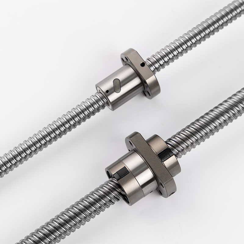
Specific environments demand peak mechanical performance. You must deploy an automation ball screw when standard drives fail to meet rigid operational standards.
Modern machine tools rely heavily on rigid mechanical drives.
Requirement: Machining centers demand sub-micron positioning. They must withstand heavy axial loads during aggressive material removal. Spindles push cutting tools forcefully into steel or titanium blocks.
Application Reality: High-rigidity, preloaded CNC automation parts eliminate backlash entirely. This rigidity ensures actual tool paths match the digital twin perfectly. When the controller commands a one-micron movement, the tool moves exactly one micron. There is no lost motion.
Industrial robots require seamless coordination across multiple axes of motion.
Requirement: Gantries need rapid point-to-point movement. They endure high duty cycles. Designers integrate these systems tightly into articulated or Cartesian frameworks.
Application Reality: Rolling-element drives serve as essential robotics components. They enable smooth, repeatable motion. You see them heavily in pick-and-place operations, welding robots, and automated inspection stations. They hold exact coordinates without suffering positional drift over millions of cycles.
Packaging lines prioritize sheer speed and continuous reliability.
Requirement: These environments demand 24/7 continuous operation. Lines process thousands of units hourly. Systems must survive high-throughput pacing without sudden failures.
Application Reality: Custom lead variations allow designers to adapt the mechanism. A higher lead (like 20mm or 25mm per revolution) prioritizes travel speed over extreme precision. This optimization perfectly matches the packaging line's aggressive pacing requirements.
Engineers frequently debate the merits of different screw drives. You must understand their underlying friction principles to make an informed choice.
The core difference lies in the contact mechanics. A Ball Screw utilizes rolling friction. Small steel spheres circulate between the nut and the screw shaft. This rolling action yields greater than 90% mechanical efficiency.
Conversely, lead screws rely on sliding friction. A polymer or bronze nut drags directly along the steel threads. This sliding contact generates significant heat. It typically yields only 20% to 50% efficiency. You must supply significantly more motor torque to move the exact same load.
Rolling friction handles intense demands beautifully. Systems using recirculating spheres support exponentially higher dynamic loads. They can run at continuous high speeds without overheating. The spheres distribute the load evenly across multiple thread pitches. Sliding friction models overheat and melt their polymer nuts if driven too fast for too long.
High efficiency brings specific operational challenges. Rolling mechanisms can back-drive under vertical loads. Because friction is so low, a heavy vertical payload will simply spin the shaft backward if motor power cuts out. Gravity pulls the load down quickly. You must incorporate supplementary braking systems in Z-axis applications.
Lead screws may be preferable for low-budget, static-holding applications. Their high friction provides a self-locking feature. If power fails, the sliding friction prevents the load from falling.
Table: Performance Comparison
Feature | Rolling Element Drive | Sliding Contact Drive |
|---|---|---|
Friction Type | Rolling (Recirculating spheres) | Sliding (Thread-on-thread contact) |
Efficiency | > 90% | 20% - 50% |
Back-Driving | High risk under vertical load (Requires brakes) | Self-locking under most conditions |
Speed Capacity | High (Continuous duty) | Low to Medium (Intermittent duty) |
Ideal Application | CNC machines, industrial robots, gantries | Manual adjustments, static vertical holding |
Selecting the proper drive requires rigorous mathematical analysis. You cannot guess component sizes. Decision makers must evaluate several critical dimensions to ensure system longevity and accuracy.
You must align the application's duty cycle with established engineering calculations.
Static Load Rating: This measures the maximum peak force the unit handles while stationary. Exceeding this rating causes permanent plastic deformation of the raceways. The spheres literally dent the steel shaft.
Dynamic Load Rating: This dictates expected lifespan under motion. Manufacturers calculate the L10 life expectancy. L10 represents the distance 90% of a given batch will travel before showing first signs of metal fatigue. You must accurately map your payload weights against these L10 charts.
Navigating standard precision grades helps control project budgets. ISO and DIN standards classify precision from C0 to C10.
C0 to C5 Grades: Manufacturers grind these shafts precisely. They offer extreme accuracy for aerospace and high-end milling.
C7 to C10 Grades: Manufacturers roll these threads under high pressure. They suit general automation and material handling perfectly.
You must match the standard precision grades to your application's tolerance requirements. Over-specifying a C3 ground shaft for a simple packaging line rapidly inflates project costs without delivering tangible benefits.
Preload eliminates frustrating mechanical play. Determining the right level of ball nut preload eliminates backlash. It increases overall system rigidity. Manufacturers achieve this by using oversized spheres or a double-nut tension system.
However, you must be careful. Higher preload increases internal friction. This generates more heat. It ultimately induces excessive wear if misapplied. Always select the minimum preload necessary to maintain your required positioning accuracy.
The operating environment dictates your protection strategy. Selecting appropriate wipers and seals is mandatory. Wipers scrape off metal chips and dust before they enter the nut housing.
Corrosion-resistant coatings protect shafts in harsh conditions. Washdown zones in food processing require special platings or stainless steel construction. Cleanrooms demand specialized low-emission greases and advanced sealing to prevent particulate contamination.
Even the best components fail if installed poorly. Theoretical performance means nothing without flawless mechanical integration on the factory floor.
Mechanical misalignment destroys drive systems rapidly. The primary cause of premature failure is radial or moment loads. These mechanisms are designed exclusively for axial (push/pull) forces.
If you push sideways on the nut, the internal spheres dig into the raceway edges. Proper selection of linear guides is absolutely mandatory. Heavy-duty profile rails must carry the payload's weight. These guides isolate the screw entirely from non-axial forces. You must align the guides and the drive shaft perfectly parallel during installation.
Metal rolling on metal requires constant lubrication. You must assess the facility infrastructure for grease versus oil lubrication.
Grease Lubrication: Suitable for most general automation. It requires periodic manual repacking or automated grease cartridges.
Oil Lubrication: Preferred for ultra-high speeds. It provides a cooling effect but requires complex plumbing and drip systems.
Failing to lubricate the raceways leads to catastrophic metal spalling. Consider the potential integration of automatic lubrication systems directly into the machine controller.
Long drive shafts present unique physical challenges. You must calculate the maximum safe operational speed to avoid screw whip. If a long, thin shaft spins too fast, it reaches its natural harmonic frequency. It begins to vibrate violently like a plucked guitar string.
Additionally, pushing a heavy load along a long shaft risks column buckling. You must determine appropriate end-support configurations. A fixed-fixed bearing arrangement holds both ends tightly. It drastically increases the critical speed and buckling limits compared to a fixed-supported arrangement.
Automated manufacturing demands uncompromising reliability from every single moving part. The right automation component carefully balances theoretical mechanical efficiency with practical operational constraints. You must evaluate loads, speeds, environments, and installation tolerances holistically.
Do not leave sizing to chance. We encourage you to download a comprehensive sizing and selection guide today. Utilize an online load calculator to check your dynamic force assumptions. Better yet, contact a dedicated application engineer to review your specific machine requirements before finalizing your bill of materials.
A: Lifespan depends entirely on operating conditions, loads, and maintenance. Engineers calculate L10 life, representing the travel distance 90% of identical units will survive before metal fatigue occurs. Proper lubrication and perfect alignment can extend a unit's life across millions of cycles, while severe side-loading can destroy it in weeks.
A: Preload introduces deliberate internal tension. Manufacturers insert slightly oversized spheres into the raceway or use two nuts pushing against each other. This internal compression removes all microscopic gaps between the threads. When the motor reverses direction, the nut responds instantly without any lost motion or hesitation.
A: Yes. You must specify appropriate environmental protections. Standard steel will rust quickly. You should request specialized anti-corrosion platings, such as Raydent or black oxide. Additionally, high-performance wiper seals are necessary to prevent water and caustic cleaning chemicals from washing away the internal grease.
A: Pneumatic cylinders rely on compressible air, causing them to bounce and struggle with exact mid-stroke stopping. Rolling-element electromechanical drives provide rigid, absolute mechanical linkages. They allow servomotors to execute highly precise, repeatable positioning profiles down to the sub-micron level, which pneumatics simply cannot achieve.


