
- All
- Product Name
- Product Keyword
- Product Model
- Product Summary
- Product Description
- Multi Field Search
Views: 0 Author: Site Editor Publish Time: 2026-07-22 Origin: Site
Modern engineering relies heavily on translating rotational motion into linear motion. Engineers constantly face the challenge of securing reliable, low-friction linear movement for high-load or high-precision applications. Over-specifying these components wastes valuable budget. Conversely, under-specifying them causes catastrophic system failure. Finding the perfect balance requires a deep understanding of mechanical drive mechanisms.
This guide moves beyond basic definitions. We provide a concrete framework for evaluating, specifying, and implementing the right mechanical drive system. You will learn the anatomical breakdown of these mechanisms. We also explore the physics of rolling friction and the critical criteria required for successful deployment. By examining load ratings, accuracy grades, and maintenance realities, we empower you to make informed engineering decisions without compromising performance. Proper implementation ensures your machinery operates smoothly and meets strict operational tolerances.
High Efficiency: Ball screws utilize rolling friction to achieve over 90% mechanical efficiency, drastically reducing the required motor torque compared to traditional sliding-friction screws.
Core Components: The system relies on a precision-machined screw shaft, a ball nut, and recirculating ball bearings to carry heavy loads smoothly.
Evaluation Mandate: Selecting the right unit requires balancing dynamic load ratings, accuracy classes, and required preload against budget constraints.
Implementation Reality: Proper lubrication and contamination protection are non-negotiable for achieving the calculated lifecycle of the assembly.
Understanding a ball screw assembly requires looking closely at its individual components. Each part plays a specific role in managing forces and facilitating smooth movement. Manufacturers engineer these elements to work together in perfect harmony. A single flaw in one component compromises the entire system.
The screw shaft acts as the foundational spine of the assembly. It features a helical raceway, or thread, cut continuously along its length. This raceway provides the track where steel balls roll. Manufacturing methods dictate the baseline precision of this shaft. Engineers typically choose between rolled and ground screws.
Manufacturers create rolled screws by forcing blank steel rods through heavy rotating dies. This cold-forming process hardens the material and offers excellent value for general automation. Alternatively, ground screws undergo abrasive machining after heat treatment. Grinding removes microscopic imperfections. It creates an incredibly precise raceway suitable for high-end aerospace or specialized manufacturing.
The ball nut serves as the primary housing mechanism. It interfaces directly with the load you want to move. Inside this nut, you will find a corresponding internal thread matching the screw shaft. However, the nut does not directly touch the shaft. Instead, it rides entirely on a layer of rolling steel bearings. This design eliminates direct metal-to-metal sliding contact. The nut also contains specialized mounting flanges or threads. These features allow you to bolt the nut securely to your moving carriage or table.
Steel balls cannot simply roll out the end of the nut. They must return to their starting position to provide continuous motion. The recirculation system handles this critical task. Without it, the bearings would collide and jam instantly.
Designs typically use either internal or external return paths. Internal deflectors force the balls to cross over the screw thread land and enter the adjacent groove. This keeps the nut compact. External return tubes route the balls outside the nut body before dropping them back into the raceway. This method easily handles large diameter bearings and high-load applications.
Precision steel balls serve as the crucial load-bearing elements. They sit snugly between the raceways of the shaft and the nut. The exact sizing of these spheres determines the overall fit and friction of the system. Manufacturers sort these balls into highly specific micron classifications.
By selecting balls slightly larger than the raceway gap, engineers introduce stiffness. This careful sizing process dictates how evenly the system distributes mechanical stress. Perfectly matched balls ensure uniform load sharing. This prevents localized wear and extends the operational life of the entire drive unit.
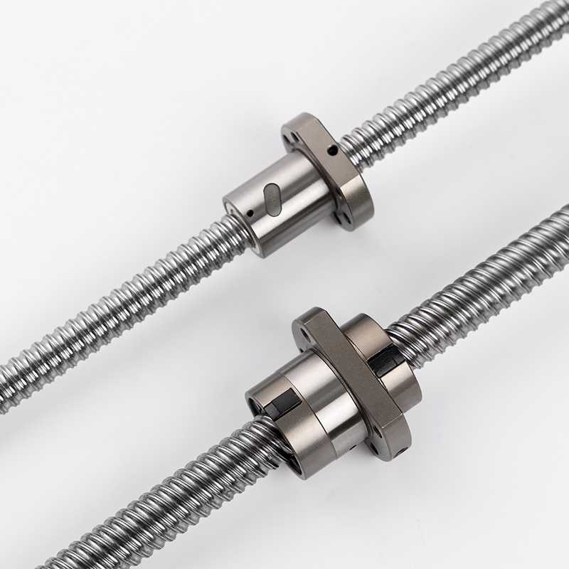
Translating rotary input into linear output requires specific mechanical interactions. A CNC ball screw relies entirely on rolling kinematics. This approach differs fundamentally from older sliding technologies. Let us explore the physics making this translation possible.
Traditional Acme or lead screws rely on sliding friction. The internal threads of their nuts drag directly against the screw shaft. This sliding action requires immense energy and generates massive amounts of heat. It also severely limits maximum operating speeds.
Rolling friction changes this dynamic entirely. Steel bearings act as tiny wheels between the nut and the shaft. They roll smoothly along the helical path. This physics principle dramatically reduces resistance. Heavy load translation happens with minimal heat generation. As a result, systems utilizing rolling elements can operate continuously without requiring extended cooling periods.
Precision systems cannot tolerate sloppy movement. Engineers must manage internal clearances carefully to maintain accuracy.
Defining Backlash: Backlash refers to the axial play or "slop" present when a screw reverses direction. If the nut changes direction, the screw might turn slightly before the load actually moves. This lost motion ruins positional accuracy during complex routing or cutting tasks.
Introducing Preload: Engineers eliminate backlash by applying preload. They force the internal components tightly against one another. One method involves inserting oversized balls into the raceway. Another uses a double-nut configuration separated by a tensioning spring or spacer. Preloading creates a rigid, highly responsive drive system capable of exact micro-positioning.
A continuous track of rolling bearings distributes mechanical stress evenly across the assembly. When a heavy load pushes against the nut, the force spreads out. It transfers through dozens of individual steel spheres simultaneously.
This even distribution minimizes the pressure exerted on any single point of the raceway. It keeps contact stresses below critical thresholds. By preventing localized material fatigue, optimal load distribution significantly extends the fatigue life of all internal components. It ensures the system operates reliably over millions of cycles.
Engineers often debate between different linear drive technologies. You must understand the practical trade-offs between rolling and sliding designs. Making the wrong choice impacts your budget, safety, and operational capabilities. A standard Ball Screw behaves very differently from a polymer lead screw.
Rolling elements deliver over 90% mechanical efficiency. Lead screws typically struggle to achieve 30% to 50% efficiency. This massive difference directly impacts your motor sizing.
Because rolling systems waste so little energy, you can drive them using much smaller, less expensive motors. Lead screws require massive torque simply to overcome their own internal sliding friction. While lead screws might seem cheaper initially, the cost of oversized motors and larger power supplies quickly negates those savings.
High efficiency brings specific design challenges. Sliding friction systems naturally resist moving under their own weight. This self-locking feature makes lead screws highly stable for lifting applications.
Rolling elements lack this friction. They will back-drive under vertical loads if the system loses power. The weight of the carriage will force the nut down, spinning the screw shaft in reverse. When designing vertical lifting mechanisms, you must implement supplemental holding brakes. Failsafe brakes prevent dangerous carriage drops during power failures.
Sliding nuts made of polymer or bronze operate very quietly. They dampen vibrations effectively. However, their friction limits them to low speeds. Fast movements melt polymer nuts rapidly.
Rolling elements handle much higher speeds effortlessly. They generate very little heat during rapid traversals. The trade-off comes in acoustic performance. The constant clatter of steel balls recirculating through tubes generates noticeable noise. Engineers must consider this acoustic footprint when designing medical devices or laboratory automation equipment.
Making the right choice requires evaluating the broader operational context. The following chart illustrates the primary trade-offs between these two drive technologies.
Evaluation Metric | Rolling Element Design | Sliding Element Design |
|---|---|---|
Mechanical Efficiency | Exceeds 90% | 30% to 50% typically |
Motor Torque Requirement | Low (Cost-effective motor sizing) | High (Requires larger, expensive motors) |
Back-Driving Risk | High (Requires external braking systems) | Low (Often inherently self-locking) |
Maximum Travel Speed | High (Generates minimal heat) | Low (Friction causes thermal expansion) |
Acoustic Profile | Moderate to Loud (Bearing recirculation) | Very Quiet (Material damping) |
You must rigorously evaluate your application before ordering components. Specifying a precision ball screw involves multiple engineering calculations. Guesswork leads to rapid mechanical failures.
You must match your application's peak and continuous forces against manufacturer load ratings. The Dynamic Load Rating (C) dictates the continuous operational limits. It represents the load under which the system will survive one million revolutions without metal fatigue.
The Static Load Rating (C0) represents the maximum load the system can handle while stationary. Exceeding the static limit causes permanent plastic deformation of the bearings. This permanent denting, known as brinelling, causes rough operation and premature spalling. Always calculate your peak shock loads against the C0 rating.
Manufacturers classify precision using ISO and JIS standards. These tolerance grades range from C0 (most precise) to C10 (least precise). You must select the grade matching your process requirements.
Standard rolled screws typically fall into the C7 or C10 categories. They work perfectly for general automation, packaging, and basic material handling. Ground screws achieve C3 or C5 classifications. They are mandatory for high-end aerospace manufacturing, precision grinding machines, and optical inspection equipment. Higher accuracy grades increase purchase costs significantly.
Every shaft has physical limitations based on its geometry and how you mount it. You must evaluate two critical failure modes.
First, evaluate the critical speed. Long, thin shafts whip violently if spun too fast. The mounting style (end-fixity) heavily influences this limit. Fixed-fixed supports allow much higher speeds than simple supported-supported arrangements. Second, calculate column buckling limits. A long shaft acting under heavy compressive loads will bow and buckle. Increasing the shaft diameter raises both the critical speed and the buckling load limits.
Operating environments aggressively attack mechanical components. You must evaluate the necessary protective measures.
Standard carbon steel rusts rapidly in humid environments. You might need specialized corrosion-resistant platings or stainless steel construction. Furthermore, harsh environments demand heavy-duty protection. Evaluate specialized wipers to scrape away metal chips or heavy dust. For cleanroom or vacuum applications, specify vacuum-compatible lubricants and low-particulate seals to maintain compliance.
Even the most perfectly specified linear motion system fails if implemented poorly. The transition from theoretical design to factory floor reality introduces severe risks. You must proactively manage lubrication, contamination, and alignment.
Proper lubrication is non-negotiable. Grease or oil serves multiple vital functions beyond simple friction reduction. The lubricant dissipates localized heat generated by internal pressure. Most importantly, it creates an elastohydrodynamic film separating the steel balls from the raceway.
Without this microscopic film, the extreme pressure causes metal surfaces to micro-weld together instantly. When the balls continue rolling, they tear these welds apart, causing severe pitting. You must establish strict Preventative Maintenance (PM) intervals. Automating the lubrication process with metered delivery blocks guarantees continuous protection.
Particulate ingress destroys precise internal geometry rapidly. Metal shavings, abrasive dust, and even hardened coolant act as grinding pastes inside the nut.
You must address the risk of contamination during the design phase. Do not rely solely on standard factory nut seals. Evaluate the necessity of external protection. High-grade bellows or telescopic way covers provide a physical barrier against debris. High-performance wiper seals offer secondary protection, aggressively cleaning the raceway before the nut passes over it.
Rotary-to-linear conversion systems handle thrust effectively. However, they possess extreme vulnerability to radial forces. You must ensure perfect alignment during installation.
Highlight the severe risk of side-loading or moment loads. These systems are designed strictly for axial loads. If the carriage misaligns, it forces the nut sideways against the shaft. This uneven pressure crushes the bearings on one side while unloading the other. Emphasize that separate linear guides must bear all radial and moment loads. The driving screw must float freely within its axial path.
Your choice of manufacturing partner impacts long-term reliability. Shortlist suppliers based on strict criteria.
Demand comprehensive testing documentation and material traceability. Ensure the supplier possesses custom machining capabilities for end-journals. Inaccurate end-journal machining introduces severe runout, vibrating the entire assembly apart. A reliable partner will provide dedicated application engineers to verify your calculations before cutting any metal.
Specifying the proper mechanical drive represents an exercise in precise engineering balance. You must carefully weigh positional accuracy requirements, dynamic load capacities, and harsh environmental protections against one another.
The successful deployment of these components relies on executing fundamental best practices. Keep these primary takeaways in mind:
Calculate dynamic and static loads meticulously to avoid premature material fatigue and brinelling.
Implement robust holding brakes on any vertical lifting application to counteract back-driving risks safely.
Separate your load paths strictly. Bear axial forces with the screw and mandate linear guides for all radial loads.
Establish rigorous lubrication and contamination prevention strategies before commissioning the equipment.
Do not leave your next automated design to chance. Consult with a specialized application engineer today. Download a professional sizing calculator to verify your preliminary numbers, or submit your specific application specifications directly for a comprehensive technical review and quote.
A: Yes, they routinely handle vertical loads in automated lifts and Z-axis CNC machines. However, their high mechanical efficiency means they lack self-locking capabilities. If power is lost, gravity will cause the load to back-drive the nut downward. You must install supplemental holding brakes or counterweights to prevent dangerous carriage drops.
A: The difference lies in the manufacturing process and resulting precision. Rolled screws are cold-formed through high-pressure dies, offering cost-effective performance for general automation. Ground screws undergo precise abrasive machining after heat treatment. Grinding produces tighter tolerance limits and exceptional accuracy, making them more expensive but necessary for high-end aerospace or specialized CNC applications.
A: Grease is typically preferred for standard speeds and horizontal orientations because it adheres well and requires less frequent maintenance access. Oil lubrication excels in high-speed applications where heat dissipation is critical. Oil is also ideal for continuous automated lubrication systems, though it requires more complex delivery plumbing and fluid recovery methods.
A: Pitch refers to the linear distance between individual consecutive threads on the shaft. Lead represents the actual linear travel distance the nut covers during one complete 360-degree rotation of the screw. Understanding the lead helps engineers calculate the exact rotational speed required from the motor to achieve the desired linear traversal speed.


