
- All
- Product Name
- Product Keyword
- Product Model
- Product Summary
- Product Description
- Multi Field Search
Views: 149 Author: Site Editor Publish Time: 2026-08-03 Origin: Site
Every automated system relies on precise mechanical foundations to function effectively. The Linear Guide serves as the foundational component for achieving high-accuracy, low-friction linear motion in modern industrial and automation applications. When you design a robotic cell or a multi-axis machining center, this hardware ensures flawless movement. However, underspecifying or misapplying a guide carries severe operational consequences. Facilities routinely experience premature wear, catastrophic machine failure, loss of machining tolerances, and expensive unplanned downtime simply because they chose the wrong configuration.
Understanding the underlying mechanics helps you prevent these costly failures. This article breaks down the mechanical principles, primary configurations, and critical engineering criteria you need to evaluate. We will detail the specific steps required to select the correct system for high-stakes applications. By following these guidelines, you will ensure optimal performance and extend your machinery's operational lifespan.
Linear guides utilize rolling elements (balls or rollers) between a block and a rail to achieve low-friction precision movement and handle high load capacities.
Selecting the optimal linear motion guide requires balancing dynamic/static load ratings, rigidity requirements, and environmental constraints.
Proper installation (specifically rail parallelism and alignment) and consistent lubrication are non-negotiable for achieving the calculated operational lifespan.
Total Cost of Ownership (TCO) is dictated less by the initial purchase price and more by integration complexity, maintenance intervals, and reliability under operational stress.
To appreciate how a linear motion guide functions, we must examine the shift from sliding friction to rolling friction. Older systems relied on plain bearings dragging across a surface. This sliding action generated excessive heat and required massive amounts of power. Modern systems eliminate this problem by using recirculating rolling elements. They drastically reduce friction, allowing machines to move heavier loads with far less energy.
Understanding the system requires examining its three primary components. Each part plays a critical role in maintaining structural rigidity and smooth operation.
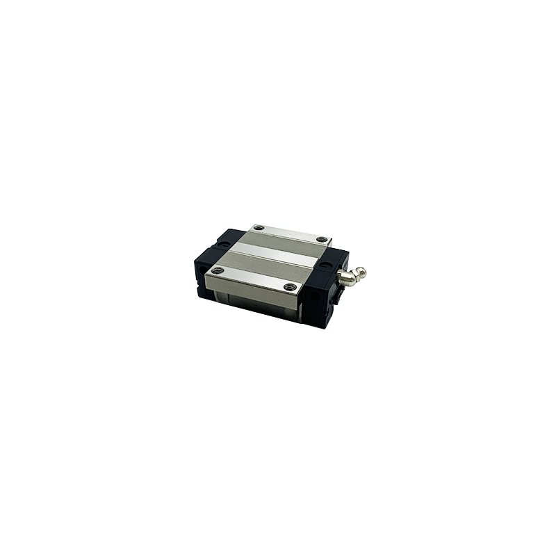
The carriage (block): This component mounts to your moving payload. It houses the complex internal recirculation system, protective seals, and lubrication ports. The carriage design ensures balls or rollers continuously cycle through the load zone without binding.
The rail: This serves as the fixed foundation. Engineers machine precision-ground tracks along the rail length. These tracks support the rolling elements as they travel.
The rolling elements: These are typically hardened steel or ceramic balls and rollers. They physically bear the mechanical load, transferring force from the carriage into the rail.
Load distribution relies heavily on the internal contact angle. The raceways inside the carriage and along the rail feature specific geometries, such as a Gothic arch or circular arc profile. This contact angle allows the guide to absorb multi-directional forces simultaneously. They effectively manage radial loads pushing down, reverse-radial loads pulling up, and lateral loads pushing from the sides. They also handle complex moment loads (pitch, yaw, and roll) while maintaining strict precision.
Industrial applications present wildly different structural and environmental demands. Manufacturers developed several distinct categories to address these varied requirements. Selecting the right category dictates the success or failure of your mechanical design.
Profiled guides offer exceptionally high load capacity and extreme rigidity. Their flat, square profile maximizes the contact area between the rolling elements and the rail track. This makes them the ideal choice for a standard CNC guide rail and heavy-duty automation equipment. However, this rigidity comes with strict implementation rules. They require highly machined, perfectly flat mounting surfaces to prevent internal binding. If you mount them on an uneven base, they will fail rapidly.
Round shaft guides prioritize flexibility over absolute load capacity. They feature a cylindrical shaft and a specialized linear bushing. They provide lower overall rigidity but offer a much higher tolerance for structural misalignment. You will find them best suited for applications featuring less rigid mounting bases. They excel in environments where self-aligning capabilities are necessary to compensate for slight frame warping.
Engineers must also choose between balls or rollers as the primary rolling element. This choice fundamentally alters the mechanical behavior of the system.
Ball-type guides: These use spherical rolling elements. They provide point contact along the raceway. This design is optimal for high-speed applications, general precision tasks, and scenarios demanding the lowest possible friction.
Roller-type guides: These utilize cylindrical rollers. They establish line contact rather than point contact. This dramatically increases the surface area bearing the load. Roller guides provide maximum rigidity and load capacity, making them essential for heavy machine tools and high-impact presses.
Proper selection goes far beyond picking a physical size. You must evaluate the guide across several strict engineering dimensions to guarantee reliable operation.
You must accurately assess both dynamic and static loads. The dynamic load rating (C) determines the calculated operational lifespan under continuous motion. Standard L10 life calculations use this value to predict when metal fatigue will naturally occur. Conversely, the static load rating (C0) represents the maximum stationary force the guide can handle. Exceeding the static rating causes permanent plastic deformation of the raceways, immediately destroying smooth operation.
Accuracy classes dictate the positional repeatability of the carriage as it travels along the rail. You must match the accuracy class (such as Normal, High, Precision, or Super Precision) to your application's requirements. High-precision CNC machines demand strict tolerances, while basic packaging equipment can utilize Normal class hardware.
Preload involves inserting slightly oversized rolling elements into the carriage. This creates an internal negative clearance. Preloading eliminates physical play (backlash) and significantly increases system rigidity. However, you must carefully determine preload levels. Excessive preload introduces unnecessary friction, generates excessive heat, and aggressively reduces the operational lifespan.
Every guide features maximum permissible speeds and acceleration limits. You must verify these parameters against your motion profile. Rapid directional changes inflict massive stress on the internal recirculation components. End caps can fracture if balls strike them at velocities exceeding the manufacturer's specified limits.
Your operating environment often dictates the final configuration. Cleanrooms require low-particle-generation greases. Washdown environments demand anti-corrosion platings, such as Raydent or hard chrome. You must also select appropriate sealing options. Standard seals keep dust out, while heavy-duty scrapers handle large metal chips and abrasive particulates.
Evaluation Dimension | Primary Consideration | Common Mistakes |
|---|---|---|
Load Capacity | Dynamic (C) vs. Static (C0) ratings | Ignoring shock loads during emergency stops |
Preload | Eliminating backlash vs. adding friction | Over-preloading, causing rapid overheating |
Environment | Corrosion resistance and sealing | Using standard carbon steel in washdown zones |
Selecting premium hardware guarantees nothing if you install it poorly. Implementation errors account for the vast majority of early mechanical failures in automation systems.
Profiled guides carry strict requirements for flat, parallel mounting surfaces. The high rigidity of a profiled block means it cannot bend or flex to accommodate a warped base. Mounting a high-precision linear guide rail on an uneven surface immediately causes internal binding. This binding forces the rolling elements to dig into the raceways. Documented industry cases show this simple error cuts the operational lifespan by up to 90 percent.
Relying solely on bolt friction to hold a rail straight is a dangerous practice. Heavy vibration or lateral impact loads will eventually shift the rail out of alignment. Best practices require using machined reference edges (datum edges) on the machine bed. You should firmly press the rail against this reference edge during installation. For extreme applications, you must use wedge profiles or lateral set screws to physically lock the rail in place, preventing any shifting under load.
The bolting process requires meticulous attention. If you tighten bolts randomly, you will induce structural distortion across the rail length. You must follow strict torque specifications provided by the manufacturer. Furthermore, you must employ a proper bolt-tightening sequence. Always start from the center of the rail and work outward toward the ends in an alternating pattern. This pushes any microscopic bowing outward, keeping the rail perfectly flat against the bed.
Long-term reliability depends almost entirely on your maintenance strategy. Even the most robustly engineered systems will fail quickly if ignored after installation.
Grease or oil starvation remains the leading cause of linear guide failure. The rolling elements require a continuous microscopic film of lubricant to prevent metal-on-metal contact. Without it, the raceways suffer catastrophic spalling and pitting. You must establish rigorous lubrication routines. Manual maintenance intervals often get forgotten in busy production environments. Therefore, we highly recommend integrating automated lubrication systems. These systems deliver precise amounts of oil or grease at calculated intervals, ensuring the carriage never runs dry.
Contaminants destroy internal components rapidly. You must evaluate the true cost of seal failure. Abrasive dust acts like lapping compound inside the carriage, wearing down the balls and reducing system preload. In environments containing heavy metal chips, abrasive dust, or coolant spray, standard seals are insufficient. You must specify bellows, telescoping covers, and double-lip end seals. Protecting the rail surface is just as important as lubricating it.
Global supply chains require smart sourcing strategies. Specifying proprietary dimensions locks you into a single vendor, exposing you to lengthy production delays. You gain a massive operational advantage by specifying globally standardized, interchangeable blocks and rails. Following ISO and DIN dimensional standards allows you to source exact replacements from multiple manufacturers. This standardization reduces replacement lead times and minimizes the spare parts inventory you must hold on site.
A linear guide is a comprehensive mechanical system, not just an isolated component. Achieving reliable, precision movement requires perfect alignment between the system's mechanical capabilities and your specific environmental realities. Neglecting surface preparation or underestimating moment loads will guarantee premature failure.
Engineering teams should formally calculate their precise load, speed, and rigidity requirements before contacting a manufacturer. By clearly defining these parameters upfront, you streamline the selection process and avoid costly over-engineering.
As a next step, we recommend utilizing the dedicated sizing software and life calculators provided by leading manufacturers. You should also download exact 3D CAD models to perform physical integration testing within your machine assemblies. Finally, consult an application engineer for complex scenarios involving custom preload parameters, harsh environments, or ultra-high precision requirements.
A: Generally no. You cannot mix them unless they are explicitly specified as interchangeable according to standard dimensions. Manufacturers utilize proprietary raceway profiles, contact angles, and manufacturing tolerances. Mixing a block from one brand with a rail from another typically results in binding, lost preload, and rapid failure.
A: Lifespan is calculated using the basic dynamic load rating (C), the applied equivalent load, and specific operational factors. These factors include travel speed, external vibration, and raceway hardness. Engineers utilize the standardized L10 life calculation formula to predict the distance the guide will travel before initial metal fatigue appears.
A: The most common causes are structural misalignment during installation, inadequate or incorrect lubrication, and external contamination. Installing a rigid rail on an uneven surface causes internal binding. Lack of grease leads to direct metal-to-metal friction, while dust entering the carriage grinds down the rolling elements.
A: Preload uses slightly oversized rolling elements to create an internal negative clearance within the carriage. It matters because it significantly increases system rigidity and eliminates physical play. While it enhances positional accuracy, it also reduces overall speed capacity and generates higher internal friction.


