
- All
- Product Name
- Product Keyword
- Product Model
- Product Summary
- Product Description
- Multi Field Search
Views: 136 Author: Site Editor Publish Time: 2026-08-07 Origin: Site
Selecting the wrong Linear Guide compromises machine precision. It accelerates component wear and quickly leads to costly unplanned downtime. In high-stakes manufacturing environments, operational integrity relies on getting this core decision right. Engineers face a delicate balance every day. You must weigh load capacity against physical footprint limitations when sourcing vital automation components. Choosing standard catalog options without understanding field conditions often results in catastrophic premature failure. We need a more systematic framework for evaluating these critical mechanisms. This guide helps you navigate strict engineering realities rather than just relying on basic catalog specifications. We will deeply explore how you can accurately match multi-directional load profiles. We will show you how to combat extreme environmental hazards effectively. Finally, we will help you set proper installation tolerances to avoid structural binding. You will learn the exact steps needed to specify a robust, high-precision system.
Selection must begin with accurate load and moment calculations, distinguishing between dynamic and static limits.
Environmental conditions (dust, temperature, chemicals) dictate sealing, plating, and lubrication choices just as much as mechanical load.
Understanding the trade-off between rigidity (preload) and friction is critical for precision applications.
Proper installation tolerances and alignment are non-negotiable for achieving the manufacturer's rated operational lifespan.
You must build a strong foundation for proper linear rail selection before looking at catalogs. You cannot specify a component safely without mapping the precise load profile first. Systems fail when engineers confuse the static load rating (C0) and the dynamic load rating (C). The static rating dictates the maximum force the block handles while stationary. The dynamic rating predicts the expected operational lifespan under continuous movement. You must also account for multi-directional forces acting on the carriage. Equipment rarely faces perfectly downward pressure. We have to calculate upward pull and lateral shifts. We must carefully measure rotational moment loads.
Load Category | Engineering Definition | Primary Impact on System |
|---|---|---|
Static Load (C0) | Maximum stationary force applied before permanent raceway deformation occurs. | Determines catastrophic failure limits during emergency stops or resting states. |
Dynamic Load (C) | Constant load under which the system travels a defined baseline distance. | Dictates the expected operational fatigue life of the internal rolling elements. |
Moment Loads | Rotational forces (pitch, yaw, roll) applied off-center from the carriage. | Causes uneven wear on ball tracks; requires high rigidity to counteract safely. |
Pitch refers to the see-saw motion along the axis of travel. Yaw describes the side-to-side twisting motion. Roll involves rotation around the axis of travel. These rotational forces put immense, uneven stress on the slider blocks.
Next, define your precision and accuracy requirements clearly. Many confuse running parallelism with repeatability. Parallelism measures how straight the block travels along the rail. Repeatability measures how accurately the system returns to the exact same position. Assess how much rigidity you actually need for the task. Over-engineering for sub-micron precision wastes budget and increases friction.
Finally, evaluate your speed and acceleration profiles thoroughly. You must determine several kinematic factors:
Maximum travel velocity during peak operation.
Average operational stroke lengths.
Acceleration and deceleration ramp rates.
High-frequency, short-stroke movements require special attention. They cause severe localized wear. The rolling elements never complete a full rotation. This leads directly to severe lubrication starvation. You must design proper greasing intervals to combat this specific issue.
Navigating the various types of an industrial linear guide is essential for optimizing machinery. The market offers several distinct architectures. Each design serves specific mechanical constraints.
Let us compare profile rail and round rail systems first.
Profile Rails: These deliver high rigidity and massive load capacity. They fit perfectly into tightly constrained spaces. However, they demand highly precise mounting surfaces. Any slight deviation in the mounting base causes immediate binding.
Round Rails: These systems are inherently more forgiving of misalignment. They flex slightly to accommodate imperfect foundations. You will find them ideal for gantry systems or less rigid framework structures.
Next, consider the internal rolling elements. You must choose between ball guides and roller guides carefully.
Ball-type guides: These use spherical balls to maintain point contact along the raceways. They generate much lower friction. They achieve significantly higher travel speeds. They work exceptionally well for most standard automated transport tasks.
Roller-type guides: These feature cylindrical rollers providing line contact instead of point contact. This line contact drastically increases maximum structural stiffness. It provides superior load capacity for heavy-duty machine tools.
You must also evaluate miniature guides for heavily constrained spaces. Engineers specify these tiny units for advanced medical devices. They power delicate semiconductor manufacturing equipment. They fit neatly inside compact electronics assembly stations. Despite their tiny size, they require rigorous load calculations. They operate on a microscopic scale where even small dust particles cause catastrophic jamming.
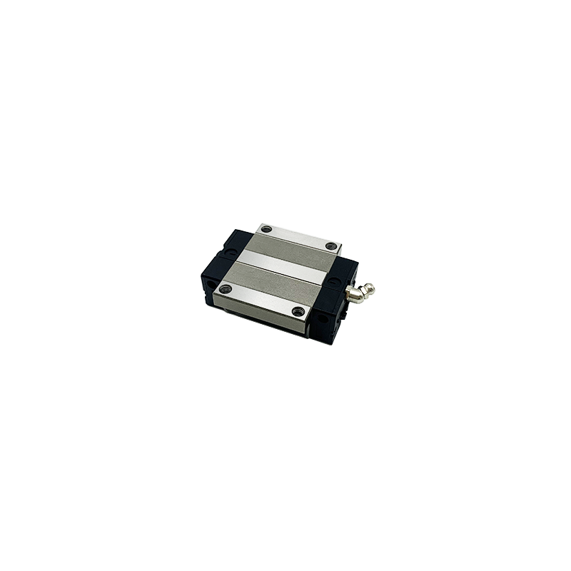
Mechanical load only tells half the story during system design. The physical operating environment dictates long-term operational success. Contamination and debris management require strict, uncompromising attention. You must evaluate specialized sealing options carefully. Standard end seals keep basic ambient dust out. However, aggressive environments demand side seals and double seal configurations.
Metal scrapers become mandatory when dealing with heavy wood dust. You also need them to clear hot metal shavings. They deflect abrasive ceramic particles safely. A scraper physically pushes heavy debris off the track. It stops debris before it reaches the delicate inner seals.
Corrosion resistance represents another major engineering hurdle. You must assess the metallurgy of your chosen system. Washdown environments in food processing require martensitic stainless steel. Harsh chemical baths demand specialized surface treatments. Engineers frequently specify Raydent coatings or hard chrome plating. These platings protect the core steel from aggressive cleaning agents. The coating permeates the metal surface to prevent rapid oxidation.
Finally, address severe lubrication and temperature realities. Extreme heat thins out standard industrial grease. Vacuum environments cause conventional lubricants to outgas. This ruins nearby optical sensors. You must select a grease viscosity tailored to your ambient temperature. Evaluate self-lubricating blocks for hard-to-reach areas. A well-designed machine guide rail often utilizes a centralized auto-lube system. This ensures continuous grease delivery. It removes reliance on inconsistent manual maintenance schedules. Proper lubrication films prevent metal-to-metal contact.
Even the highest quality components fail if you install them incorrectly. Misalignment and mounting surface inaccuracies rank as leading causes of failure. Profile rails require exceptionally flat mounting beds. Poor surface flatness creates immediate binding during travel. This excess friction drastically reduces the Mean Time Between Failures (MTBF). Always machine your mounting surfaces to match exact manufacturer tolerances. Prevent tolerance stacking during structural assembly.
Specifying the wrong preload introduces another massive operational risk. Preload removes physical clearance by using slightly oversized rolling elements. It increases overall system rigidity. However, requesting maximum preload for basic transport tasks is a dangerous mistake. It generates unnecessary friction and excessive heat. This leads directly to premature raceway wear. Only specify heavy preload when dealing with heavy vibrations. Use it when machining exceptionally hard metals.
You must never ignore the system level relationship between rails and bearings. Some engineers try mixing slider blocks and rails from different production batches. They sometimes even mix components from different manufacturers entirely. This destroys geometric precision instantly. It introduces microscopic misalignments between the ball track and the block. Doing this always voids your manufacturer warranty. Buy them as factory-matched sets. This guarantees proper internal clearance and smooth operational travel.
Choosing the right supply partner matters just as much as the component itself. Effective shortlisting goes far beyond flipping through specification catalogs. You need robust prototyping capabilities and deep engineering support from your vendor.
Look for manufacturers providing accessible, high-quality 3D CAD models. Clear sizing software saves weeks of manual calculation time. It helps verify your dynamic load assumptions quickly via digital simulation. Furthermore, you need highly responsive application engineering support. A custom machine sometimes acts unpredictably during early prototyping. A knowledgeable vendor engineer proves invaluable in these moments. They help troubleshoot structural resonance issues. They identify optimal kinematic greasing strategies tailored to your exact cycle times.
Supply chain stability and system scalability determine your long-term success. You must carefully assess vendor lead times for various configurations. Standard rail lengths usually ship quickly from regional warehouses. However, custom-cut lengths face severe delays. Specialized block configurations often require long manufacturing lead times.
Establish strict criteria for mechanical standardization across your entire facility. Prioritize interchangeable ISO-dimensioned guides. Using universally dimensioned components simplifies future procurement drastically. It allows your maintenance team to swap out parts rapidly without custom machining. This standardized approach keeps scaling efforts smooth. It ensures predictable operations as your production demands increase over time.
Choosing the right guide requires a deeply holistic engineering view. Mechanical loads dictate the core physical dimensions of the blocks. Environmental hazards determine the necessary seals, scrapers, and protective platings. Implementation tolerances dictate the ultimate lifespan of the entire mechanical assembly. You cannot treat these precision devices as simple interchangeable commodities.
Take immediate, calculated action on your next design project. Consult directly with an application engineer to review your moment load calculations. Download a reputable sizing calculator to verify your expected operational life. Request physical product samples for testing in your actual manufacturing environment. Thorough upfront validation always prevents costly downstream failures.
A: You calculate it using the standard L10 life formula. This formula divides the dynamic load rating by the applied equivalent load. You then cube this ratio for ball-type elements, or use an exponent of 10/3 for roller types. Multiply the result by 50km or 100km, depending on the manufacturer's baseline. This yields the expected travel distance before metal fatigue begins.
A: Clearance is the physical microscopic gap between the rolling elements and the raceway. It allows slight play and easy movement. Preload is an intentional internal force applied using slightly oversized rolling elements. It eliminates all internal backlash and significantly increases structural stiffness, though it raises friction.
A: Yes, you can mount them upside down or vertically. However, you must recalculate all moment loads to account for the new orientation. You also need to address gravity's effect on lubrication flow, as grease may pool at the bottom. Implement fail-safe braking mechanisms to prevent sudden drops.
A: Lubrication intervals depend heavily on travel speed, applied load, and environmental hazards. Typically, you should regrease them every 100km of travel, or every 3 to 6 months. Always follow the specific manufacturer nomograms provided in their manuals to ensure optimal film thickness is maintained.


