
- All
- Product Name
- Product Keyword
- Product Model
- Product Summary
- Product Description
- Multi Field Search
Views: 0 Author: Site Editor Publish Time: 2026-07-28 Origin: Site
Selecting the wrong linear motion components compromises machine tool precision. It severely limits feed rates during production. It also accelerates mechanical wear across your entire system. Engineers and retrofitters face a complex reality every day. You must navigate a vast matrix of accuracy grades. You must balance preload configurations against dynamic load capacities. Guesswork here often leads to premature failure. It creates heavily bloated budgets and ruined production schedules. We built this guide to help you cut through the technical noise. Our goal is to provide an evidence-based framework for your next build. You will learn how to specify the exact linear drive configuration you need. We will align your choice directly to your CNC machine’s strict performance requirements. You can achieve your lifecycle goals effectively without overspending. Read on to master the sizing process. Prevent catastrophic design mistakes before they ever reach your shop floor.
Application dictates specs: Machining hard metals requires different rigidity and preload levels compared to high-speed wood or plasma routing.
Accuracy isn't everything: Over-specifying ISO/JIS grades (e.g., demanding C0 when C5 suffices) exponentially increases costs without guaranteed ROI.
Preload is critical for CNC: Eliminating backlash requires proper ball nut preload, which inherently affects friction and operating temperatures.
Mounting matters: The configuration of end supports (fixed-fixed vs. fixed-supported) directly impacts critical speed and buckling limits.
Assess the operational workload thoroughly. Machining hard metals demands specific mechanical capabilities. Heavy climb milling imposes massive radial and axial loads on your drive systems. It requires high dynamic load capacity. It demands absolute rigidity from your mechanical assemblies to prevent tool chatter. Rapid positioning creates an entirely different challenge. High-speed wood routers or plasma cutters prioritize high lead and rapid acceleration. They rarely see heavy cutting forces. You must differentiate these profiles early in your design phase. Overlooking these forces leads to rapid bearing degradation.
Next, identify standard versus high-precision needs clearly. Map your required part tolerance directly to standard machine tool components. Standard rolled screws offer an excellent cost-to-benefit ratio. They dominate basic automation tasks and general manufacturing. Precision ground screws cost significantly more. However, they deliver superior positioning repeatability. Analyze whether your final product actually needs aerospace-level accuracy. Do not pay for a +/- 0.005mm tolerance if your end product allows +/- 0.1mm deviations.
Map the physical constraints of your machine chassis. Define the maximum stroke length first. Check your available footprint for the nut housing and bearing blocks. Determine your integration limits regarding servo or stepper motors. Ensure you have enough clearance for motor mounts and rigid couplings. If you ignore these spatial limits, installation becomes a nightmare. Re-machining heavy cast iron bases wastes valuable engineering time and delays deployment.
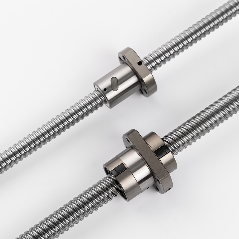
The JIS, DIN, and ISO grading systems measure cumulative lead error. Grades like C3, C5, and C7 dictate positioning accuracy over specific travel distances. A C7 grade easily handles basic automation. It works exceptionally well for general wood routers and 3D printers. However, a C5 or C3 grade remains mandatory for a high precision ball screw. Aerospace and medical CNC machining demand these tighter tolerances to meet stringent compliance rules. Over-specifying your grades ruins project budgets quickly. Understand your true manufacturing baseline.
Screw diameter correlates directly to column strength. Thicker screws resist buckling under heavy axial loads. They also delay the onset of critical speed whipping over long spans.
Lead, or pitch, measures travel distance per revolution. This creates a direct tradeoff between mechanical resolution and travel speed. High lead means faster travel during rapid traverse movements. Yet, it inherently lowers your mechanical advantage. It also reduces positional resolution. Choose your lead based on your motor's optimal RPM range. Balancing torque curves against desired speeds yields the best results.
You must match the basic dynamic load rating to your expected machine duty cycle. We call this rating Ca. This calculation yields the theoretical fatigue life. Engineers refer to this as L10 life, representing the point where 90 percent of identical units survive. Static load ratings matter mostly during crash events or heavy tool plunging. Ensure your continuous dynamic loads stay well below the component's maximum limits.
Oversized balls eliminate internal clearances physically. They wedge tightly into the gothic arch profile of the threads. Double-nut configurations use a tension spacer between two independent nuts. Lead-offset preloading shifts the thread pitch slightly during manufacturing. Proper CNC ball screw selection balances these exact methods. Increased preload eliminates backlash entirely. It guarantees tight tolerances during axis reversal. However, it generates more friction and heat. You will require stricter lubrication protocols to survive this increased thermal load.
Rolling contact creates a massive mechanical advantage. Our discussed components offer up to 90 percent mechanical efficiency. Sliding-contact lead screws typically hover between 30 and 50 percent efficiency. This directly impacts your motor sizing requirements. High friction wastes electrical energy as heat. It forces you to buy larger, more expensive servo motors to achieve the same traverse speeds.
An automation screw utilizing recirculating bearings resists wear beautifully. It maintains zero-backlash properties significantly longer under continuous CNC cycling. Acme threads wear down much faster because of sliding friction. This continuous sliding degrades the softer bronze or polymer nut material constantly. This rapid wear requires frequent software pitch compensation to maintain accurate part sizes. Eventually, software cannot fix physical slop.
We must provide balanced, trustworthy advice. Some specific applications require natural back-driving resistance. Vertical Z-axes without electromagnetic holding brakes present a major safety risk. Heavy spindle heads can drop instantly if shop power fails. Highly contaminated environments destroy precision bearings quickly. Tight engineering budgets might also force compromises. In these specific cases, an acme or lead screw might be the safer choice. They resist back-driving naturally due to their high friction coefficient.
Long, thin shafts face major operational risks. Do not specify them for high-speed feeds without thorough calculations. Exceeding the critical speed causes resonance in the shaft. This triggers catastrophic whipping vibration and rapid mechanical failure. Shaft sagging on horizontal spans exacerbates this issue.
Common mistakes to avoid during design:
Ignoring horizontal shaft sag on spans exceeding two meters.
Pushing spindle drives past their maximum rated critical RPM.
Failing to calculate the unsupported length properly during the design phase.
Choosing improper end supports for the desired traverse speeds.
End machining represents a harsh engineering reality. Mounting styles dictate your performance ceiling directly. How you support the shaft determines its maximum speed and buckling load.
Mounting Style | Rigidity Level | Max Speed / Buckling Load | Alignment Difficulty |
|---|---|---|---|
Fixed-Free | Lowest | Very Low | Easy |
Fixed-Supported | Moderate | Medium | Moderate |
Fixed-Fixed | Highest | Very High | Extremely Difficult |
Fixed-Free setups provide the lowest RPM and load capacity. They only support the motor end. Fixed-Supported setups offer a moderate middle ground. They allow slight thermal expansion while preventing whipping. Fixed-Fixed setups deliver the absolute highest rigidity possible. However, they remain the hardest to align properly. Misalignment here destroys support bearings instantly due to binding.
Improper lubrication causes massive reliability issues. Ingress of metal chips causes equal damage. These two factors drive 90 percent of premature mechanical failures. You must integrate proper felt or plastic wipers into the nut housing. Use robust protective bellows or way covers in harsh CNC environments. Clean lithium soap base grease extends component life exponentially. Contaminated grease acts exactly like lapping compound, grinding away your precision profiles.
Buying off-the-shelf lengths cuts lead times drastically. It also reduces upfront engineering costs. You can integrate them into prototypes quickly. Ordering custom end-machined screws offers perfect fitment for your proprietary castings. It ensures optimal bearing journal concentricity. However, it adds weeks to delivery schedules. Weigh your timeline against your internal machining capabilities. Small shops often benefit from pre-machined standard lengths.
Find suppliers who offer robust technical tools. Look for comprehensive sizing calculators and downloadable 3D CAD models. Application engineering support proves vital for complex load verifications. Good vendors review your L10 calculations thoroughly. They flag potential critical speed issues early. They guide you toward the right preload configurations for your specific spindle horsepower.
Gather your operational data now. Note your maximum load, overall travel length, and duty cycle. Define your desired rapid traverse speed clearly. Contact a technical sales team. Verify your L10 life calculations before issuing a purchase order. Protect your investment through rigorous peer review and vendor collaboration.
Successful integration balances theoretical math against real-world shop floors. The most expensive drive component will still fail eventually if installed poorly. Misaligned end supports destroy precision rapidly. Neglected grease fittings ruin perfect installations within weeks.
Match your preload levels directly to your target material hardness.
Always calculate critical speeds for long-axis spans before finalizing designs.
Prioritize heavy contamination defense in dirty shop environments.
Consult your internal engineering team to verify spatial constraints.
Take action today to secure your machine's reliability. Download a comprehensive sizing guide from a trusted component vendor. Submit your specific CNC machine specifications for an expert technical review. Secure your mechanical foundation before you begin assembly.
A: Manufacturing methods dictate the primary difference. Rolled screws are extruded through heavy dies. They cost less and suit standard automation tasks perfectly. Ground screws are precision-machined using abrasive grinders. They cost significantly more but offer extreme positioning accuracy. Ground variants typically achieve C5 to C0 accuracy grades, making them ideal for strict aerospace tolerances.
A: You eliminate backlash by introducing mechanical preload. You can use oversized bearings inside the nut to fill clearances. Alternatively, install a double-nut system with a tension spacer. If backlash suddenly appears in an older machine, check your bearing blocks first. Worn support bearings often mimic nut backlash perfectly.
A: Exceeding critical speed causes severe whipping. The long shaft begins to vibrate uncontrollably at its resonant frequency. This harmonic distortion destroys positional accuracy instantly. It also induces massive radial loads on the end supports. Premature wear, severe noise, and catastrophic mechanical failure will quickly follow.
A: Lubrication intervals depend entirely on your specific duty cycle. Heavy continuous milling requires daily or weekly greasing. Light routing might only need monthly checks. Always follow the manufacturer’s baseline volume recommendations. Dirty environments demand more frequent flushing to expel debris. Use automated lubricators to prevent human error entirely.


